Patrol 4x4 - Nissan Patrol Forum banner

ZD30 Di glow plug timer mod

64K views 112 replies 32 participants last post by  jono6974  
#1 · (Edited)
ZD30 Di GLOW PLUG TIMER MOD


If you own a 2000 – 2006 ZD30 Di patrol this is a mod for you.
This mod is wired slightly differently to the other ones and is designed to work with the newer Kemo timers.

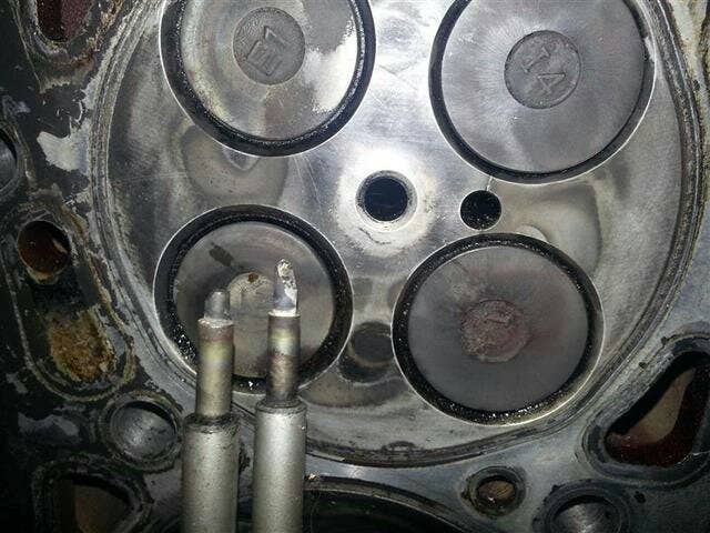
The ZD30 Di ECU keeps the glow plugs on for 5 minutes after you start the car unless the engine is already at operating temperature. Heads are cracking between the glow plugs and the valves. This can be at either of the 4 glow plugs or all of them. Main symptom is coolant getting pushed out of the coolant top-up tank that is attached to the header tank. When bad it pressurises the cooling system faster and higher than normal. It can also assist your radiator seals to fail.
The ceramic tipped OEM glow plugs are also prone to failure. Once you have installed the timer you can use steel tipped glow plugs which are a ¼ of the price of the OEM ones.
With the Kemo timer you can set the glow time 30 seconds and avoid cracks. It is fully automatic and is controlled by the car’s ECU so you just start the car as normal.
Image

Head cracked between the glow plug and valves. Left hand glow plug tip was found embedded into a piston.


PARTS REQUIRED: (EVERY ITEM IS AVAILABLE AT JAYCAR)
KEMO 12V DC TIMER MODEL M117A
12V RELAY
3.25M WIRE
10 X FEMALE SPADE TERMINALS
1 X LOOP TERMINAL
2 X 40MM LONG SHRINKWRAP
1 x INLINE FUSE

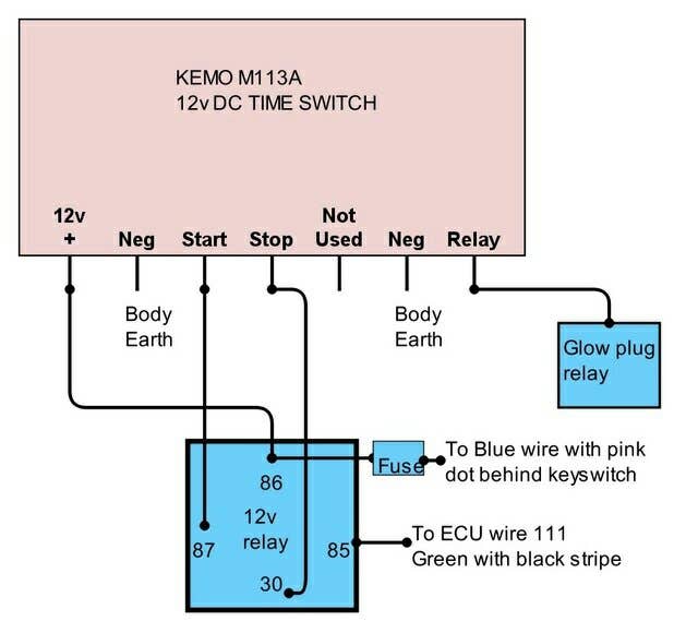
SCHEMATIC
Image
.
METHOD

1. Cut 6 pieces of wire 50cm long.
2. Cut 1 piece of wire 75cm long.
3. Disconnect battery.
4. Remove ECU harness from ECU with 10mm socket.
5. Remove white plastic cover from plug using small screwdriver to push lugs.
6. Remove short split tube section from connector.
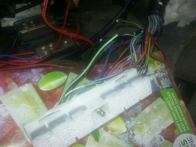
7. Locate GREEN wire with Black stripe from pin 111 on ECU connector.
8. Cut wire about 7cm from connector.
9. Solder and heatshrink 50cm long wire to wire from connector. Connect to pin 85 on relay.
10. Solder and heatshrink 50cm long wire to green/black wire heading to glow plug relay. Connect to relay pin on Kemo.

11. Replace white plastic cover and split tube. Wrap with electrical tape and reinstall ECU harness.

12. Use 50cm long wire to connect Start pin on Kemo to pin 87 on relay.

13. Use 50cm long wire to connect Stop pin on Kemo to pin 30 on relay.

14. Use 2 x 50cm long wire to connect both earths to single ring terminal. Connect ring terminal to earth under dash. (Bolt at bottom of steering column is fine.)

15. Undo 5 x screws and remove steering column cover taking care not to damage the NATS key reader ring at ignition switch.

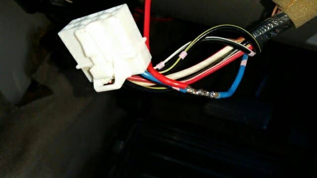
16. Locate Blue wire with pink dot at back of ignition switch.

17. Strip and solder 75cm long wire to Blue/pink wire. Cover joint with electrical tape. Run wire down to near ECU connector. Connect inline fuse to end of cable.

18. Reinstall Steering column cover.

19. Connect inline fuse and a 50cm long wire to a single terminal. Connect to pin 86 on relay. Connect 50cm long wire to 12v + pin on Kemo.

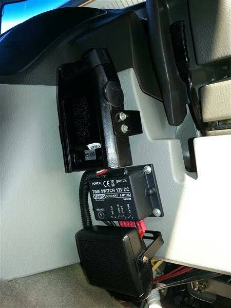
20. Mount Kemo timer to lower part of dash using 4 screws or double sided tape.

21. Use split tube or electrical tape to loom up wires between Kemo timer and relay.

22. Connect battery.

23. Turn on ignition until dash lights up for a few seconds and look for two lights on top of Kemo timer. Green light means Kemo is powered up. Red light indicates glow plugs are powered on.


24. Use a small flat blade screwdriver to adjust time on Kemo. Anticlockwise is shorter time. Clockwise is longer time. Start with dial almost all the way anticlockwise. Turn on ignition until dash lights up and time how long the red light is on. Adjust until it is around 30sec.

25. Test for power at glow plug rail to ensure timer mod is functional.
Image

Kemo timer installed on dash
Image

Blue wire with pink dot soldered to wire running to kemo.
Image

Green wire with black stripe cut and about to be soldered.
 
Discussion starter · #16 ·
So if the timer failed and you reconnected 85 on the Relay and the Relay plug back together on the Kemo the system would be back to normal. But wouldnt the glow plugs then be controlled by the ECU and be on for too long?

By the way the system is working really well.
Yes. Connecting the wire from 85 back to wire from relay on kemo will have it back to ecu control again until you fix it.
Having said that. I've never heard of one failing.

Sent from my SM-G900I using Tapatalk
 
Discussion starter · #20 ·
Very keen to do this to my rig, thanks for the write up mate. All looks quite straight forward. I have been practicing my soldering skills lately.

Question: On steps:
7. Locate GREEN wire with Black stripe from pin 111 on ECU connector.
8. Cut wire about 7cm from connector.
9. Solder and heatshrink 50cm long wire to wire from connector. Connect to pin 85 on relay.

Do we just leave the other end of the green and black stripe wire? We ONLY wire/solder the connection end and hook it to the relay?

And can I confirm this is for the Kemo switch M113A with model number 24024OM. As I have seen Geeyous video variation where his older serial number wiring did not work with the newer. Cheers mate!!
The other end of that wire is dealt with in step 10.
"10. Solder and heatshrink 50cm long wire to green/black wire heading to glow plug relay. Connect to relay pin on Kemo"

Yes. This version is designed to work with the newer models. Ive done several using the 24024OM.

Sent from my SM-G900I using Tapatalk
 
Discussion starter · #29 ·
I will be installing the Kemo timer soon following skegbudley's 20-04-2016 post: beautifully clear !! Thanks; very useful !!
Just 2 questions:
Would a 10A fuse be OK ?
Where best fit the relay ? (the place where to fit the timer seems OK to me)
A 10amp fuse will be fine.
As for the relay. It will sit under the ECU on the transmission tunnel.
 
Discussion starter · #35 ·
have had a glowplug switch for years....simple connection from ECU to redlit toggle....if its cold i turn them on, wait a few secs, start, turn off. Why install a timer?
Because it is set and forget just like factory.
Most people also have partners, kids and mates drive their car too. Having it totally automatic means that the car starts like normal.
It's costs less than $50 and only takes a extra 45min to do
Why not do it?
 
Discussion starter · #44 ·
I've had issues with cheaper relays in the past causing wierd faults. Work perfectly well on spotlights but spaz out on the timer circuit.
 
Discussion starter · #48 ·
Hi Skegbudley,

Thanks for the great post. About to embark on this myself as I've just done a full engine rebuild on a 2000 Patrol and want to avoid the cracking I had across all 4 cylinders and the tip of the glow plug the embedded itself in the head and top of the piston!

A few questions if you don't mind, I am looking to steal some of the wiring points from http://www.patrol4x4.com/forum/3-litre-zd30-di-engine-71/gu-iv-glow-plug-timer-mod-189290/ but using the Kemo;

- The green wire with black stripe. Is this the wire that is connected to the glow plug relay and is grounded by the ECU in factory setup? Yes it is. End going to ECU goes to 85 on relay. End going to glow plug relay goes to relay port on Kemo.
- When the relay is activated it appears to close the normally open circuit between pin 30 & 87 basically connecting the start and stop pins on Kemo to each other. Is this correct? Yes this is correct. If so I don't understand how/why that works (I sure it does, I just don't understand).
- Step 16. Locate Blue wire with pink dot at back of ignition switch.
What is this wire? Is it just an ignition switched +12V feed? If so I assume we could pick this up from anywhere. It is a ignition switched circuit that does not have a power cut during startup like most others. One of the problems we found with the later timers is they are very sensitive to when power is applied. Using this wire fixes the problem.

I want to also use the in dash lamp as Lemo does in the link I provided above. I'm thinking I could add another relay that is grounded by the relay pin on the Kemo timer to ground the dash light via a 2.2k resistor. You are best off running a wire from the glow plug bus bar to a indicator lamp so you definitely know when power is on or off.

Thanks in advance, Craig.
I've been meaning to look into the other wiring method to see if access to the glow plug wire is easier. Have a Kemo install either this weekend or next so I will look at it then.
 
Discussion starter · #51 ·
First post edited with replacement pics.


While I'm here. Here is a different way of doing the mod. Both the timer and relay are mounted inside the box with both LEDs exposed for diagnostic purposes. I still have a LED on the dash wired directly to the glow plug busbar.
Image


ZD30 rules the road.
 
Discussion starter · #77 ·
ok then, thought i was on a winner,

BUT....

wired up timer, all went well. tried to set timer to 30 seconds but could only get 3 seconds then jump to 50 seconds, no big deal i can live with that i think, i do recall someone saying it is very touchy.

BUT....

after glowing and light goes out then starting engine it starts to glow again, light comes back on, red light, checked bus bar and definitely has power.

all wired as per geeyoutoo's diagram in previous post.

any ideas...??
Where are you powering the timer from?

ZD30 rules the road.
 
Discussion starter · #79 ·
cigarette lighter, only comes on with ignition
That's your problem. The cigarette power turns off whilst the engine is cranking. This will restart the timer.
The correct wire is the blue one with the pink dot behind the ignition switch. Go back to the first page of this thread and have a read. There is a pic of the wire there.

ZD30 rules the road.
 
Discussion starter · #82 ·
ok i think i'm all sorted, sourced power from the wire quoted and seems to be doing what its supposed to be doing, just cant find that sweet spot , i was going for 30 seconds as geeyoutoo has but cant do any better than 50 , as soon as i adjust down it goes to 5,

50 seconds not to harsh is it ??
Good one.
Not too harsh but 30 would be better. Keep trying.

ZD30 rules the road.
 
Discussion starter · #85 ·
don't panic everyone, all done, timer resetting was probably due to weakened battery after trying to set it for a lengthy period of time, finally got timer set for 33 seconds, close enough for me.

at ease all....
Sweet as mate. [emoji106]

ZD30 rules the road.
 
Discussion starter · #91 · (Edited)
Hi I have set up the kemo timer what amp relay should I use, I had a 40amp red light was going out around 30 seconds and now it is staying on


If you own a 2000 – 2006 ZD30 Di patrol this is a mod for you.
This mod is wired slightly differently to the other ones and is designed to work with the newer Kemo timers.

The ZD30 Di ECU keeps the glow plugs on for 5 minutes after you start the car unless the engine is already at operating temperature. Heads are cracking between the glow plugs and the valves. This can be at either of the 4 glow plugs or all of them. Main symptom is coolant getting pushed out of the coolant top-up tank that is attached to the header tank. When bad it pressurises the cooling system faster and higher than normal. It can also assist your radiator seals to fail.
The ceramic tipped OEM glow plugs are also prone to failure. Once you have installed the timer you can use steel tipped glow plugs which are a ¼ of the price of the OEM ones.
With the Kemo timer you can set the glow time 30 seconds and avoid cracks. It is fully automatic and is controlled by the car’s ECU so you just start the car as normal.
Image

Head cracked between the glow plug and valves. Left hand glow plug tip was found embedded into a piston.


PARTS REQUIRED: (EVERY ITEM IS AVAILABLE AT JAYCAR)
KEMO 12V DC TIMER MODEL M117A
12V RELAY
3.25M WIRE
10 X FEMALE SPADE TERMINALS
1 X LOOP TERMINAL
2 X 40MM LONG SHRINKWRAP
1 x INLINE FUSE

SCHEMATIC
Image
.
METHOD

1. Cut 6 pieces of wire 50cm long.
2. Cut 1 piece of wire 75cm long.
3. Disconnect battery.
4. Remove ECU harness from ECU with 10mm socket.
5. Remove white plastic cover from plug using small screwdriver to push lugs.
6. Remove short split tube section from connector.
7. Locate GREEN wire with Black stripe from pin 111 on ECU connector.
8. Cut wire about 7cm from connector.
9. Solder and heatshrink 50cm long wire to wire from connector. Connect to pin 85 on relay.
10. Solder and heatshrink 50cm long wire to green/black wire heading to glow plug relay. Connect to relay pin on Kemo.

11. Replace white plastic cover and split tube. Wrap with electrical tape and reinstall ECU harness.

12. Use 50cm long wire to connect Start pin on Kemo to pin 87 on relay.

13. Use 50cm long wire to connect Stop pin on Kemo to pin 30 on relay.

14. Use 2 x 50cm long wire to connect both earths to single ring terminal. Connect ring terminal to earth under dash. (Bolt at bottom of steering column is fine.)

15. Undo 5 x screws and remove steering column cover taking care not to damage the NATS key reader ring at ignition switch.

16. Locate Blue wire with pink dot at back of ignition switch.

17. Strip and solder 75cm long wire to Blue/pink wire. Cover joint with electrical tape. Run wire down to near ECU connector. Connect inline fuse to end of cable.

18. Reinstall Steering column cover.

19. Connect inline fuse and a 50cm long wire to a single terminal. Connect to pin 86 on relay. Connect 50cm long wire to 12v + pin on Kemo.

20. Mount Kemo timer to lower part of dash using 4 screws or double sided tape.

21. Use split tube or electrical tape to loom up wires between Kemo timer and relay.

22. Connect battery.

23. Turn on ignition until dash lights up for a few seconds and look for two lights on top of Kemo timer. Green light means Kemo is powered up. Red light indicates glow plugs are powered on.


24. Use a small flat blade screwdriver to adjust time on Kemo. Anticlockwise is shorter time. Clockwise is longer time. Start with dial almost all the way anticlockwise. Turn on ignition until dash lights up and time how long the red light is on. Adjust until it is around 30sec.

25. Test for power at glow plug rail to ensure timer mod is functional.

Image

Kemo timer installed on dash
Image

Blue wire with pink dot soldered to wire running to kemo.
Image

Green wire with black stripe cut and about to be soldered.
[/QUOTE] i use a 30a Narva relay. part number 72386.
Sorry I accidentally left that out.

I like shiny stuff
 

Attachments

Discussion starter · #95 ·
i use a 30a Narva relay. part number 72386.

Sorry I accidentally left that out.


I like shiny stuff


I am using kemo timer m113A but red light stays on I’m swapping it with another new on tomorrow form jaycar

Image


Sent from my iPhone using Tapatalk[/QUOTE]Have seen several weird failures over the last 6 months. Hopefully the new one works better for you.

I like shiny stuff