ZD30 Di GLOW PLUG TIMER MOD
If you own a 2000 – 2006 ZD30 Di patrol this is a mod for you.
This mod is wired slightly differently to the other ones and is designed to work with the newer Kemo timers.
The ZD30 Di ECU keeps the glow plugs on for 5 minutes after you start the car unless the engine is already at operating temperature. Heads are cracking between the glow plugs and the valves. This can be at either of the 4 glow plugs or all of them. Main symptom is coolant getting pushed out of the coolant top-up tank that is attached to the header tank. When bad it pressurises the cooling system faster and higher than normal. It can also assist your radiator seals to fail.
The ceramic tipped OEM glow plugs are also prone to failure. Once you have installed the timer you can use steel tipped glow plugs which are a ¼ of the price of the OEM ones.
With the Kemo timer you can set the glow time 30 seconds and avoid cracks. It is fully automatic and is controlled by the car’s ECU so you just start the car as normal.
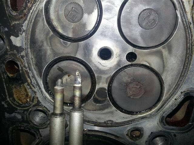
Head cracked between the glow plug and valves. Left hand glow plug tip was found embedded into a piston.
PARTS REQUIRED: (EVERY ITEM IS AVAILABLE AT JAYCAR)
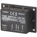
KEMO 12V DC TIMER MODEL M117A
12V RELAY
3.25M WIRE
10 X FEMALE SPADE TERMINALS
1 X LOOP TERMINAL
2 X 40MM LONG SHRINKWRAP
1 x INLINE FUSE
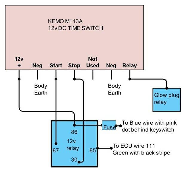
SCHEMATIC
METHOD
1. Cut 6 pieces of wire 50cm long.
2. Cut 1 piece of wire 75cm long.
3. Disconnect battery.
4. Remove ECU harness from ECU with 10mm socket.
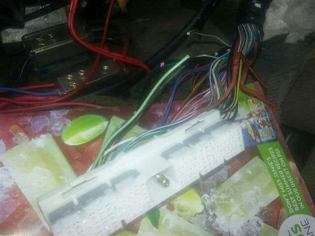
5. Remove white plastic cover from plug using small screwdriver to push lugs.
6. Remove short split tube section from connector.
7. Locate GREEN wire with Black stripe from pin 111 on ECU connector.
8. Cut wire about 7cm from connector.
9. Solder and heatshrink 50cm long wire to wire from connector. Connect to pin 85 on relay.
10. Solder and heatshrink 50cm long wire to green/black wire heading to glow plug relay. Connect to relay pin on Kemo.
11. Replace white plastic cover and split tube. Wrap with electrical tape and reinstall ECU harness.
12. Use 50cm long wire to connect Start pin on Kemo to pin 87 on relay.
13. Use 50cm long wire to connect Stop pin on Kemo to pin 30 on relay.
14. Use 2 x 50cm long wire to connect both earths to single ring terminal. Connect ring terminal to earth under dash. (Bolt at bottom of steering column is fine.)
15. Undo 5 x screws and remove steering column cover taking care not to damage the NATS key reader ring at ignition switch.
16. Locate Blue wire with pink dot at back of ignition switch.
17. Strip and solder 75cm long wire to Blue/pink wire. Cover joint with electrical tape. Run wire down to near ECU connector. Connect inline fuse to end of cable.
18. Reinstall Steering column cover.
19. Connect inline fuse and a 50cm long wire to a single terminal. Connect to pin 86 on relay. Connect 50cm long wire to 12v + pin on Kemo.
20. Mount Kemo timer to lower part of dash using 4 screws or double sided tape.
21. Use split tube or electrical tape to loom up wires between Kemo timer and relay.
22. Connect battery.
23. Turn on ignition until dash lights up for a few seconds and look for two lights on top of Kemo timer. Green light means Kemo is powered up. Red light indicates glow plugs are powered on.
24. Use a small flat blade screwdriver to adjust time on Kemo. Anticlockwise is shorter time. Clockwise is longer time. Start with dial almost all the way anticlockwise. Turn on ignition until dash lights up and time how long the red light is on. Adjust until it is around 30sec.
25. Test for power at glow plug rail to ensure timer mod is functional.
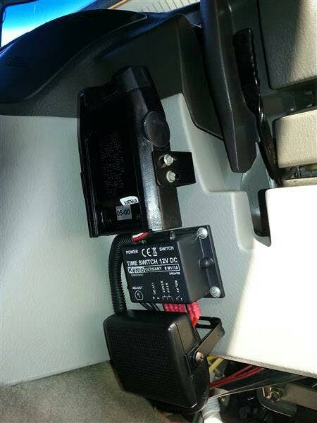
Kemo timer installed on dash
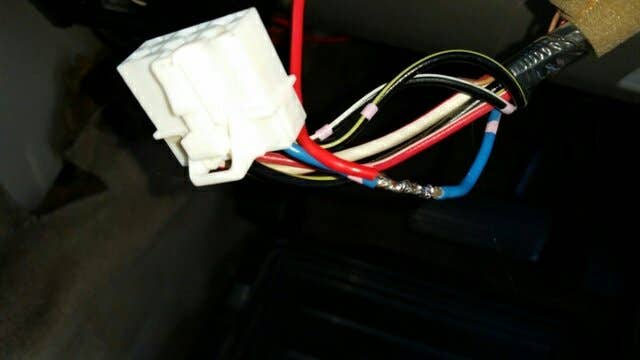
Blue wire with pink dot soldered to wire running to kemo.
Green wire with black stripe cut and about to be soldered.
") .
.